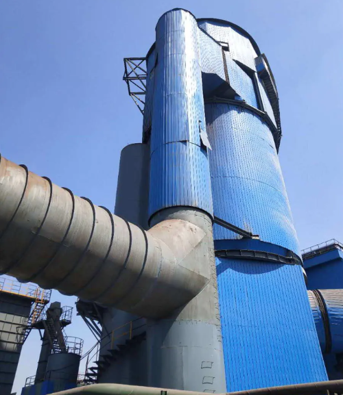
A wet scrubber designed for flue gas desulfurization (FGD) is industrial equipment that removes sulfur dioxide (SO2) and other harmful pollutants from exhaust gas streams before they enter the atmosphere. These systems represent one of the most proven and widely deployed technologies in environmental compliance, particularly for power plants, refineries, and chemical manufacturing facilities that process high-sulfur feedstocks.
Unlike dry or semi-dry alternatives, wet FGD scrubbers utilize liquid solvents—typically limestone slurry—to chemically absorb SO2 from flue gas. The process occurs in a large tower vessel where countercurrent contact between gas and liquid maximizes removal efficiency. The absorbed sulfur dioxide is subsequently oxidized and converted into sellable gypsum byproduct, transforming a liability into a commercial opportunity.
Key Components of a Wet Scrubber Tower
A complete wet FGD system comprises several critical sections working in concert:
Absorber Tower: The main reaction vessel where flue gas and limestone slurry make contact. This tower is typically constructed from reinforced concrete or stainless steel to resist corrosive SO2-laden gas and acidic conditions.
Slurry Preparation System: Mills and mixing equipment that grind limestone (CaCO3) into fine particles and hydrate them into a stable slurry with proper consistency and concentration.
Oxidation Air System: Forced air injection that catalyzes the oxidation of calcium sulfite to calcium sulfate (gypsum), allowing byproduct recovery and preventing scaling inside the absorber.
Mist Eliminator: Removes entrained liquid droplets from treated gas before discharge, preventing water loss and corrosion in downstream ductwork.
Gypsum Dewatering System: Separates and dries the gypsum product for disposal or commercial sale to wallboard manufacturers and other industries.
Recirculation Pump: Continuously circulates scrubbing liquor through spray nozzles at the top of the absorber, ensuring efficient countercurrent contact with rising flue gas.
Wet Scrubber vs. Dry Scrubber: What's the Difference?
The fundamental distinction between wet and dry FGD technologies lies in the physical state of the sorbent and the mechanism of pollutant capture:
Feature
Wet FGD
Dry FGD
Sorbent State
Limestone slurry (liquid)
Lime powder or spray-dried slurry
SO2 Removal Efficiency
95–99%
90–95%
Byproduct Recovery
Gypsum (sellable, 95%+ purity)
Fly ash (mixed, lower market value)
Water Consumption
High (500–1000 m³/hour typical)
Very low (evaporative only)
Footprint
Larger (tower height 40–60 m)
Compact
Capital Cost
Moderate to high
Higher initial investment
Operating Cost
Moderate (reagent + water)
Lower (less reagent needed)
Wet FGD systems are preferred in regions with stringent SO2 emission standards and where gypsum byproduct sales offset operational costs. Dry systems excel where water availability is constrained or waste disposal is a priority.
How Does Limestone-Gypsum Wet FGD Work?
The limestone-gypsum process represents the globally dominant wet desulfurization technology because of its simplicity, cost-effectiveness, and the marketability of gypsum byproduct. Understanding the chemistry and mechanics is essential for facilities operators and procurement professionals evaluating system options.
The Chemical Reaction Behind SO2 Removal
When flue gas containing SO2 contacts limestone slurry, a series of irreversible chemical reactions occur:
Step 1 – Dissolution and Acid Neutralization: Limestone (calcium carbonate, CaCO3) reacts with acidic SO2 and water to form calcium sulfite (CaSO3) and carbon dioxide. The limestone dissolves in the acidic environment, creating abundant hydroxide ions that buffer the slurry pH at optimal levels (5.0–5.5).
Step 2 – Oxidation to Gypsum: Injected oxidation air converts calcium sulfite (CaSO3) to calcium sulfate (CaSO4). This oxidation step is thermodynamically favorable and is typically completed within 2–8 minutes, depending on air flow rate and slurry residence time. Oxidation is critical because gypsum exhibits superior crystallization properties compared to sulfite, reducing scale formation on internal surfaces and enabling easier mechanical dewatering.
Step 3 – Crystal Growth and Separation: Over hours of residence in the absorber and clarifier tanks, calcium sulfate dihydrate (gypsum) crystals grow and settle. The clarified liquid is recycled back to the top of the absorber, while the gypsum slurry is conveyed to a vacuum filter or centrifuge for dewatering and stacking.
Step-by-Step Process Inside the Absorber Tower
The physical and chemical transformation occurs continuously in the absorber tower:
Flue Gas Inlet: Hot flue gas (typically 120–150°C from the boiler or industrial furnace) enters the bottom of the absorber tower at controlled velocity, usually 3–4 m/s, to avoid excessive pressure drop while ensuring thorough mixing.
Spray Zone: Limestone slurry is sprayed from multiple nozzles positioned at the top and mid-height of the tower. The slurry breaks into fine droplets, creating enormous interfacial contact area between gas and liquid.
Reaction Zone: SO2 diffuses into the liquid film surrounding each droplet and reacts with dissolved limestone. Droplets fall under gravity while rising flue gas carries them upward, creating a countercurrent cascade that extends residence time and drives diffusion kinetics.
Oxidation Zone: Air is injected at the bottom through spargers, bubbling upward through the absorber. Oxygen oxidizes sulfite to sulfate in the bulk liquid and within the falling droplets, converting the product to more stable gypsum.
Collection Zone: Saturated liquid accumulates in the sump at the tower base. Solids settle, allowing clarified liquid to be pumped back to the top of the tower for recirculation, while settled solids drain toward the gypsum dewatering circuit.
Gas Exit: Treated flue gas (with SO2 reduced by 95–99%) rises to the mist eliminator at the top, where entrained water droplets are removed by demisting packing or chevron mist eliminators. The cleaned gas then vents to the atmosphere or enters downstream pollution control equipment.
The entire cycle—from SO2 capture to oxidation to gypsum recovery—typically requires 8–12 minutes of slurry residence time, depending on limestone particle size, pH control strategy, and target removal efficiency. Smaller particle limestone (80–90% passing 325 mesh) accelerates reaction rates and allows operators to achieve higher efficiency at lower slurry flow rates.
Why Choose Wet FGD Technology for Your Plant?
The decision to invest in wet FGD systems reflects both regulatory necessity and operational economics. Facilities handling high-sulfur fuels or serving markets with stringent air quality standards find wet systems offer superior returns when all factors are considered holistically.
Industries That Rely on Wet Scrubbers
Wet FGD technology is foundational across multiple industrial sectors:
Coal-Fired Power Generation: The largest application globally. Modern utility boilers burning bituminous or sub-bituminous coal containing 1–3% sulfur depend on wet FGD for compliance with SO2 emission limits, which in many regions are mandated below 50–100 mg/Nm³.
Oil Refining: Fuel oil desulfurization units and coker boilers generate SO2-rich exhaust requiring high-efficiency scrubbing. Refineries often integrate wet FGD with selective catalytic reduction (SCR) for combined SO2 and NOx control.
Chemical and Petrochemical Manufacturing: Facilities producing sulfuric acid, sulfur-based polymers, or processing high-sulfur crude oil streams operate wet scrubbers to capture SO2 emissions from thermal oxidizers, calcination units, and roasting furnaces.
Pulp and Paper Mills: Recovery boilers burning black liquor produce substantial SO2 emissions. Kraft pulp mills increasingly deploy wet FGD systems to achieve regional air quality standards and reduce SO2-related air pollution in residential areas.
Metals Processing: Smelting operations extracting copper, nickel, zinc, and other non-ferrous metals from sulfide ores generate SO2-laden off-gases requiring 99%+ removal efficiency. Wet FGD is the industry standard for these applications.
Waste-to-Energy and Biomass Combustion: Municipal solid waste incinerators and biomass power plants produce heterogeneous flue gas compositions. Wet FGD provides robust, adaptable SO2 control across varying fuel quality.
Key Performance Factors: Efficiency, pH, and L/G Ratio
Achieving consistent, high-performance SO2 removal depends on controlling several interdependent parameters. Understanding these factors enables operators and engineers to optimize system design and operation:
SO2 Removal Efficiency (Target: 95–99%): Efficiency is primarily driven by two mechanisms: (1) the amount of limestone slurry circulated relative to flue gas volume, expressed as the liquid-to-gas (L/G) ratio, and (2) the residence time of gas in the absorber. Modern systems routinely achieve 95% removal at L/G ratios of 5–8 L/m³, and 98–99% efficiency at ratios of 10–15 L/m³. Diminishing returns apply—pushing beyond 15 L/m³ yields minimal efficiency gains while dramatically increasing pumping power, slurry preparation costs, and water consumption.
pH Control (Optimal: 5.0–5.5): The slurry pH directly affects limestone dissolution rate and SO2 absorption kinetics. At pH below 4.5, limestone dissolves readily but SO2 absorption slows due to reverse reactions and reduced driving force for gas-phase diffusion. Above pH 6.0, limestone solubility decreases, while SO2 absorption accelerates—but the risk of scale formation and gypsum precipitation on tower internals increases exponentially. Operators maintain pH by carefully dosing limestone slurry addition rates and oxidation air flow. Automated pH control via real-time probes has become standard practice in modern installations.
L/G Ratio (Liquid-to-Gas Volume Ratio): This dimensionless parameter—typically reported as liters of circulated slurry per cubic meter of flue gas—is perhaps the single most critical control variable. Higher L/G ratios increase slurry contact area and residence time, boosting efficiency but escalating power consumption, reagent consumption, and water loss to evaporation. The optimal L/G ratio balances regulatory compliance targets with operational cost minimization. Regional air quality standards, fuel sulfur content, and boiler load fundamentally dictate the L/G setpoint.
Gas Velocity (Typical: 3–4.5 m/s): The vertical velocity of flue gas through the absorber vessel influences droplet suspension, residence time, and pressure drop. Higher velocities reduce vessel cross-section and capital cost but increase pumping duty and erosion risk. Lower velocities increase residence time and efficiency but require larger vessels. Most operators maintain 3.5–4.0 m/s as the engineering sweet spot.
Oxidation Air Rate (Typical: 60–90% theoretical oxygen): Excess oxygen in the injected air drives sulfite-to-sulfate conversion, but excessive aeration increases foam formation and liquid carryover. Air sparger design and depth of submersion critically influence mixing and oxidation kinetics. Undersized air systems result in incomplete oxidation, sulfite precipitation, and blinding of dewatering equipment.
Wet FGD System Process Flow Diagram
Factors to Consider When Selecting a Wet Scrubber Supplier
Procurement decisions for wet FGD systems require careful evaluation of multiple technical, commercial, and operational criteria. The following factors will significantly impact system performance, longevity, regulatory compliance achievement, and total cost of ownership.
Material Selection and Corrosion Resistance
The internal environment of a wet FGD absorber is inherently corrosive: pH ranges from 3.5 to 6.0, temperatures reach 60–70°C, and dissolved SO2 and sulfurous acid accelerate metal oxidation. Material selection is not an afterthought but a foundational design decision:
Reinforced Concrete with Rubber Lining: The dominant material choice for large utility-scale absorbers. Concrete provides structural strength and thermal mass; a 10–20 mm thick rubber (neoprene or EPDM) lining protects concrete from chemical attack. Proper surface preparation and curing of rubber lining extends service life to 20–30 years with minimal maintenance.
Stainless Steel (Austenitic Grades): Favored for smaller systems, spray towers, and demisting sections due to superior corrosion resistance and cleaner design aesthetics. 316L stainless steel resists pitting in acidic chloride-bearing slurries. Trade-offs include higher capital cost (2–3x concrete) and potential for crevice corrosion if design tolerances are loose.
Thermoplastic Materials: Fiber-reinforced plastics (FRP) and polyester-based composites are emerging in niche applications and retrofit markets due to excellent chemical resistance and zero corrosion risk. Long-term durability data remains limited; thermal cycling and UV exposure in outdoor installations present unknown risks.
Spray Nozzle Materials: Spray nozzles experience the highest wear rates. Ceramic or hardened steel tips with tungsten carbide overlays resist abrasion from suspended limestone particles. Routine nozzle inspection and replacement every 2–5 years is standard operating practice.
Customization and After-Sales Support
Every industrial facility has unique flue gas characteristics, space constraints, and operational requirements. A reliable supplier will offer genuine customization rather than one-size-fits-all packages:
Site-Specific Engineering: Evaluate whether the supplier conducts detailed gas stream analysis—measurement of SO2 concentration, NOx levels, particulate loading, moisture content, and temperature profile. This data feeds into computational fluid dynamics (CFD) modeling to predict slurry distribution, gas residence time, and efficiency at your specific operating conditions. Suppliers offering laboratory-scale testing or pilot-plant data for your fuel type and gas composition demonstrate engineering rigor.
Modular Scalability: For facilities with growth potential or phased expansion plans, systems designed with modular absorber sections or parallel-train architecture allow incremental capacity addition without full-system replacement. Confirm whether internals (distributors, mist eliminators) can be retrofitted or upgraded within the existing vessel.
Integration with Existing Infrastructure: Wet FGD systems interface with boiler exhaust ducting, ID fans, precipitators, and downstream stacks. Suppliers should provide detailed ductwork and foundation designs, certifications for seismic loads if applicable, and coordination with your equipment vendors. Hidden costs frequently emerge from ductwork modifications and supports.
Training and Knowledge Transfer: Operation and maintenance of wet FGD systems require operator expertise in pH management, slurry rheology, oxidation air control, and gypsum dewatering. Select suppliers offering comprehensive on-site training, O&M manuals, spare parts availability, and emergency support hotlines. Remote diagnostics capability and predictive maintenance agreements increasingly differentiate premium suppliers from commodity vendors.
Reagent Sourcing and Logistics: Limestone availability, pricing, and transportation logistics critically impact operating costs. Suppliers should document nearby limestone sources, volume discounts, delivery schedules, and backup supply arrangements. Similarly, confirm gypsum handling infrastructure—dewatering equipment capacity, storage facilities, and downstream market connections (wallboard, cement, agriculture) that enable cost recovery.
Spare Parts Ecosystem: Identify critical wear items (nozzles, gaskets, pump impellers, mist eliminator cartridges) and confirm availability, lead times, and pricing through the supplier's network. Long-term spare parts availability for 20–30 year system lifespans requires suppliers with established distribution channels and inventory policies.
Operational Excellence: Monitoring and Control Systems
Modern wet FGD systems are sophisticated instruments requiring continuous monitoring and dynamic parameter adjustment to maintain target removal efficiency while minimizing operating costs. Advanced control systems transform wet scrubbers from passive compliance tools into actively optimized assets.
Real-Time Monitoring Technology
Real-time feedback loops enable rapid response to changes in fuel quality, boiler load, or atmospheric conditions:
Continuous SO2 Analyzers: Infrared or electrochemical SO2 sensors upstream and downstream of the absorber quantify real-time removal efficiency. Target setpoints (typically 50–100 mg/Nm³ outlet) automatically adjust limestone feed rates and L/G ratios to maintain compliance margins without excessive reagent consumption.
pH Probes: Submersed pH electrodes in the absorber sump and clarifier provide moment-to-moment slurry acidity feedback. Automated lime milk addition systems maintain pH within ±0.2 units of setpoint, preventing both scaling (high pH) and inadequate limestone dissolution (low pH).
Pressure Drop Monitoring: Differential pressure cells across the absorber, demister, and outlet ducting indicate plugging, scale formation, or mist eliminator saturation. Early warning systems trigger cleaning cycles or maintenance alerts before performance degradation accelerates.
Oxidation Air Control: Oxygen content sensors and air flow meters ensure optimal oxygen availability for sulfite oxidation. Closed-loop oxidation air control prevents incomplete conversion (requiring expensive downstream liquid-phase oxidation chemicals) and foam formation (which increases carryover).
Recirculation Pump Monitoring: Vibration sensors, bearing temperature probes, and power consumption tracking detect early-stage impeller wear, bearing degradation, or cavitation. Predictive maintenance alerts enable proactive component replacement before catastrophic failure.
Load-Following Capabilities
Industrial facilities rarely operate at constant boiler load. Wet FGD systems must accommodate turndown ratios of 40–100%, maintaining compliance and efficiency across this operating envelope. Key design features enabling load-following include:
Variable Frequency Drives (VFD): VFD-equipped recirculation pump and oxidation air fan motors scale flow rates proportionally with boiler load, reducing power consumption and reagent usage during low-load operation. VFDs easily achieve 20–30% energy savings versus fixed-speed motors with throttling control.
Multi-Stage Spray Nozzles: Systems with independently controlled spray headers at multiple tower elevations allow efficient distribution across part-load conditions. Lower loads activate fewer nozzles, maintaining optimal slurry droplet suspension and gas residence time without excessive mist carryover.
Bypass and Bleed Streams: Slurry bypass lines and clarifier bleed configurations allow granular control of residence time and pH without shutting down the entire system during turndown. Strategic bleed flow prevents overly rapid pH increase during low-load periods when gas volume and SO2 loading decline simultaneously.
Regulatory Compliance and Environmental Performance
SO2 emission limits vary globally but trend universally toward stringency. Wet FGD systems are the primary technology enabling compliance with modern standards, which in developed regions mandate outlet SO2 concentrations of 50–100 mg/Nm³ or absolute SO2 mass loading reductions of 85–99% depending on fuel type and facility class.
Global SO2 Standards Overview
Regional regulatory frameworks drive technology selection and operating strategy:
European Union: Large Combustion Plants Directive (LCPD) and Industrial Emissions Directive (IED) mandate 97–99% SO2 reduction efficiency for coal-fired and oil-fired units. Monthly average outlet concentrations must not exceed 50 mg/Nm³ for most utilities. These stringent limits necessitate high-efficiency wet FGD systems with advanced oxidation control.
United States: Clean Air Act regulations limit SO2 emissions via the National Ambient Air Quality Standards (NAAQS). Most regulatory regimes translate to outlet limits of 50–90 mg/Nm³ or 90% removal efficiency. States with nonattainment areas may impose tighter restrictions on power plants and refineries.
China and India: Rapid industrialization and growing air quality awareness have prompted adoption of wet FGD on new coal-fired capacity. Mandatory SO2 removal exceeds 90% for large units; many new installations target 95%+ efficiency to future-proof against anticipated tightening.
Japan and South Korea: Pioneering nations in wet FGD technology development, these countries enforce 80–90% removal efficiencies with low outlet concentrations (30–50 mg/Nm³). Technology maturity and operator expertise are exceptionally high in these markets.
Beyond SO2: Co-Benefits and Multi-Pollutant Control
Modern wet FGD systems simultaneously control multiple air pollutants, offering economies of scope for environmental compliance:
Particulate Matter Removal: Limestone slurry acts as a natural scrubbing medium for fly ash, removing 40–70% of inlet particulate without dedicated electrostatic precipitators or baghouses. This co-removal reduces downstream equipment burden and disposal costs.
Acid Mist and HCl Capture: Alkaline slurry neutralizes hydrochloric acid vapors (HCl) and sulfuric acid mist (H2SO4) formed from SO2 oxidation or present in fuel chlorine. Integrated wet FGD systems capture these acid gases, preventing them from reaching the atmosphere.
Mercury Speciation Influence: While wet FGD does not directly remove elemental mercury (Hg⁰), the oxidizing environment and limestone slurry promote oxidation of Hg⁰ to divalent mercury (Hg²⁺), which is subsequently captured by downstream baghouses or ESP units. This indirect pathway improves overall mercury control efficiency.
Synergy with Selective Catalytic Reduction (SCR): Power plants and refineries increasingly deploy integrated SO2-NOx control trains combining wet FGD with SCR units. The low outlet temperature from the FGD absorber (saturated, ~60°C) requires reheating before SCR catalyst to maintain activity. Strategic heat integration between the boiler and FGD/SCR systems optimizes energy efficiency and reduces operating cost.
Frequently Asked Questions About Wet FGD Scrubbers
Q1: What is the SO2 removal efficiency of a wet scrubber?
Limestone-gypsum wet FGD systems routinely achieve 95–99% SO2 removal efficiency under optimized operating conditions. The exact efficiency depends on several factors: (1) L/G ratio (higher ratios increase efficiency but add cost), (2) slurry pH (optimal range 5.0–5.5), (3) limestone particle size (finer particles dissolve faster), (4) gas residence time in the absorber (typically 8–12 minutes), and (5) oxidation air availability (complete conversion of sulfite to gypsum). Most modern systems are designed for 95–97% efficiency as a compromise between regulatory compliance and operational economics. Achieving 98–99% efficiency requires higher L/G ratios (12–15 L/m³) and tighter process control but is routinely implemented in regions with stringent air quality standards.
Q2: How much water does a wet FGD system consume?
Water consumption in limestone-gypsum wet FGD systems is substantial and represents a major operational cost in water-scarce regions. Typical consumption ranges from 500 to 1,500 m³/hour for a 500 MW coal-fired power unit, depending on flue gas volume, slurry recirculation rate, and evaporative losses. Of this total, approximately 30–40% is consumptive (lost to evaporation and gypsum crystal water), while 60–70% is recycled within the slurry circuit. Alternative technologies exist for water-constrained facilities: dry FGD systems consume only evaporative water (~5% of wet system consumption), but at the trade-off of reduced efficiency and loss of valuable gypsum byproduct. Some facilities employ water recycling loops, cooling towers, and condensation recovery to reduce net consumption.
Q3: What is the difference between a spray tower and a packed bed scrubber?
Both spray towers and packed bed scrubbers are classified as "wet" FGD technologies, but they differ significantly in internal design and operational characteristics. Spray towers (also called "spray absorbers" or "countercurrent spray contactors") distribute limestone slurry through nozzles at the top of the vessel, creating a falling spray that contacts rising flue gas. This design is simple, robust, tolerant of suspended solids, and easy to scale. Packed bed scrubbers contain structured or random packing media (ceramic saddles, plastic rings, structured sheets) that increase interfacial contact area between gas and liquid. Packed beds achieve higher removal efficiency at lower L/G ratios (6–8 L/m³ versus 10–15 for spray towers) but are more prone to scaling, plugging, and require finer limestone particles. For coal-fired power plants and industrial furnaces with high ash loading and variable gas composition, spray towers dominate due to reliability and maintainability. Packed beds are preferred in smaller, more controlled applications (refineries, chemical plants) where feed gas composition is consistent and stringent efficiency targets demand compact designs.
Q4: What is limestone (CaCO3) and why is it used as the primary reagent?
Limestone is a naturally occurring mineral (calcium carbonate, CaCO3) composed of ancient seashell and skeletal debris. It is abundant globally, inexpensive ($8–15 per ton delivered), and readily available from quarries near most industrial facilities. Limestone's primary advantage is its chemical reactivity with acidic SO2; when ground to fine particles (100–300 micrometers) and suspended in water, it rapidly dissolves in the acidic environment of the absorber sump, releasing hydroxide ions that absorb SO2 and buffer slurry pH. Lime (CaO or hydrated lime Ca(OH)2) is an alternative reagent offering faster kinetics and higher concentration, enabling lower L/G ratios and smaller vessels. However, lime's higher cost ($30–50 per ton), caustic nature, and handling hazards make limestone the default choice for most applications. Hybrid systems using limestone as the primary reagent with lime addition for pH correction during startup or upset conditions offer operational flexibility at minimal added cost.
Q5: How long does a wet FGD system last, and what are typical maintenance intervals?
Well-designed and properly maintained wet FGD systems have service lives of 20–30 years, comparable to the host boiler or industrial furnace. Critical components have shorter lifespans: rubber lining in concrete vessels (15–25 years), spray nozzles (2–5 years), recirculation pump seals and impellers (5–8 years), oxidation air spargers (8–10 years). Mist eliminator cartridges typically require replacement every 2–4 years depending on dust loading. Scheduled maintenance intervals include quarterly inspections of spray nozzles and distributor pipes, semi-annual pH probe calibration, annual rubber lining condition assessment, and biennial hydrostatic testing of pressure vessels. Predictive maintenance programs utilizing vibration analysis, thermography, and real-time performance monitoring increasingly reduce unscheduled downtime and extend component life. Proper chemical balance, corrosion inhibitor dosing, and biocide treatment (where applicable) are essential for maximizing system longevity.
Q6: Can wet FGD scrubbers handle variations in fuel sulfur content?
Yes, limestone-gypsum wet FGD systems are inherently robust to fuel sulfur variations, which represent one of their key advantages. The system adjusts limestone feed rate and L/G ratio to accommodate higher or lower SO2 loading without switching chemistry or operational mode. If fuel sulfur increases from 1.5% to 3.0% by weight, the SO2 concentration in flue gas roughly doubles. Operators respond by increasing limestone slurry circulation rate or raising limestone concentration in the slurry, maintaining target pH and outlet SO2 concentration. Conversely, when lower-sulfur fuel is burned, limestone feed is reduced proportionally. This adaptability is crucial for facilities blending multiple fuel sources, managing fuel quality variations in imported coal, or adjusting to seasonal fuel availability. Dry FGD systems lack this flexibility and typically require reagent chemistry changes or burner adjustments to maintain compliance when fuel sulfur shifts significantly.
Q7: What happens to the gypsum byproduct, and is it truly valuable?
Gypsum produced in limestone-gypsum wet FGD systems is chemically and physically identical to mined natural gypsum. High-purity gypsum (95%+ calcium sulfate dihydrate) is a premium feedstock for wallboard (drywall, plasterboard) manufacturers, representing approximately 70–80% of total gypsum demand globally. Market prices fluctuate between $5–15 per ton depending on location, purity, and logistics, but in most regions, gypsum sales offset 10–30% of wet FGD operating costs. Some facilities achieve full cost recovery through gypsum sales, particularly those with co-located wallboard plants or ports enabling export. Lower-purity gypsum (85–95% calcium sulfate) finds outlets in cement production, soil conditioning, road base stabilization, and other lower-value applications. A small percentage of FGD-produced gypsum is landfarmed or disposed in permitted facilities where markets are distant or transportation uneconomical. The convertibility of SO2 waste into commercial product—rather than combustion byproduct requiring disposal—is a unique environmental and economic advantage of the limestone-gypsum technology.
Q8: What are the main operational challenges in wet FGD system management?
Despite their robustness, wet FGD systems present several recurring operational challenges that require skilled management: (1) Scaling and Plugging: If pH rises above 5.5, calcium sulfate and calcium sulfite precipitate on internal surfaces, reducing flow and efficiency. Strict pH control and regular mechanical cleaning prevent this. (2) Corrosion Attacks: Rubber lining degradation or concrete spalling occurs if chemical balance is neglected or bypass occurs. Routine inspections and corrosion inhibitor programs mitigate risk. (3) Foam Formation: Excessive oxidation air or surfactant-bearing fuel additives promote foam, which increases carryover and water loss. Antifoam chemistry and optimized air sparger design resolve this. (4) Gypsum Dewatering Challenges: High moisture content in gypsum product increases disposal or transportation costs. Vacuum filter optimization, centrifuge adjustment, and polymer dosing improve cake dryness. (5) Intermittent Reagent Supply: Limestone sourcing disruptions or weather-induced transportation delays can force temporary compliance risk. Redundant supplier relationships and onsite storage buffering mitigate this. Experienced operators view these challenges as manageable through preventive maintenance, real-time monitoring, and proactive troubleshooting.
Conclusion: Investing in Sustainable Industrial Emissions Control
Wet flue gas desulfurization technology stands as the proven, reliable foundation for industrial SO2 emissions control across power generation, refining, metals processing, and chemical manufacturing. Achieving 95–99% SO2 removal efficiency, converting waste into marketable gypsum byproduct, and maintaining compatibility with existing boiler infrastructure, limestone-gypsum wet scrubbers represent an optimized balance between environmental performance, operational economics, and technical maturity.
The decision to implement or upgrade wet FGD capacity requires a holistic evaluation of fuel quality, regulatory obligations, facility footprint, water availability, and long-term operational cost targets. No single "universal" system design exists; instead, site-specific engineering, material selection, and control strategy adaptation ensure optimal performance for your unique industrial context.
Whether you operate a utility power plant, petroleum refinery, metals smelter, or specialty chemical facility, engaging qualified suppliers with proven track records, comprehensive technical support, and transparent performance guarantees is essential. Demand detailed engineering studies, pilot-scale performance data for your specific gas stream, transparent reagent sourcing plans, and training commitments before finalizing procurement decisions.
Need a customized wet scrubber solution for your facility's unique flue gas composition and emissions targets? Engage a supplier capable of comprehensive gas stream analysis, CFD modeling, on-site pilot testing, and long-term performance guarantees. Provide detailed specifications of your fuel type, SO2 concentration, gas flow rate, temperature profile, and target removal efficiency, and request a preliminary engineering proposal and cost estimate. Most qualified suppliers deliver feasibility assessments within 2–4 weeks, enabling rapid evaluation and informed procurement decisions.



 English
 Français
 عربى
عربى 简体中文
简体中文