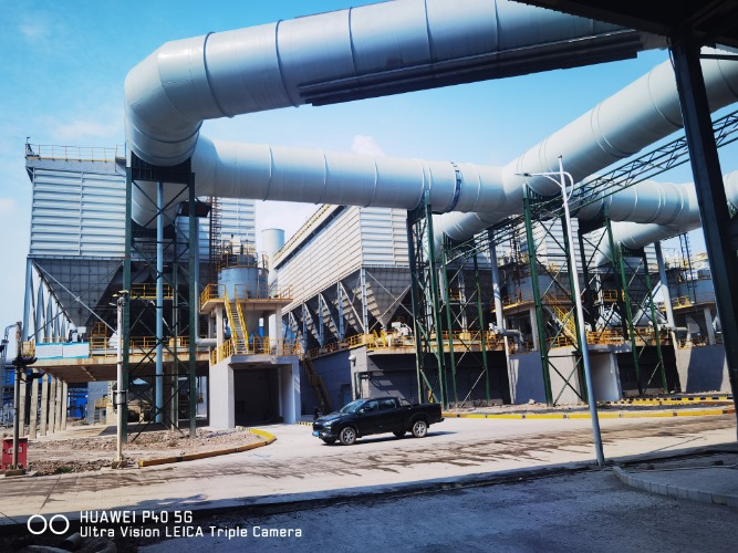
Relocating a dust collection system is rarely a simple matter of lifting equipment from one spot and setting it down in another. When the source is a lime kiln, the job becomes a chain of interlocking engineering problems: hot and humid flue gas, abrasive and sticky dust, tight plant geometry and a production line that cannot stay idle for long. A successful dust collector relocation depends on understanding every one of these constraints before a single bolt is turned.
This article walks through the practical steps of a lime kiln dust collector relocation project, from the first site survey through to commissioning and post-project performance. The aim is to show engineers and plant managers how the decisions were made, why certain trade-offs were accepted, and what the measured outcomes looked like once the system was running again.
Relocation is a process-engineering task, not only a materials-handling task.
Flue gas temperature, dew point and dust chemistry drive most design decisions.
Modular fabrication and short shutdown windows protect kiln output.
Measured emissions and pressure stability are the true measures of success.
Project Background and Core Challenges
The plant operated a lime kiln whose existing dust removal equipment had reached the end of its useful layout. Production expansion and a site reorganization meant the collector had to move to a new location within the same plant footprint. The client set three priorities: keep emissions within the local particulate limit after the move, avoid extended kiln shutdowns, and preserve enough operating margin for future maintenance.
High-Temperature Flue Gas From the Lime Kiln
Lime kiln exhaust is among the more demanding gas streams for any fabric filter. Gas temperatures commonly sit well above ambient, carry a load of fine calcium-based dust, and contain moisture and acid-forming components that can condense on cooler surfaces. If the gas temperature drops toward its dew point inside ducts or the housing, the dust cake becomes sticky, bags blind quickly and pressure drop climbs. Condensation also accelerates corrosion of steel shells and hoppers.
Design work therefore started with a detailed characterization of the gas stream, including peak and average temperature, moisture content, dust loading and particle size distribution. These figures set the operating window for the filter media and the insulation scheme.
Strict Site Space Limitation During Relocation
The new location offered less clearance than the original installation. Existing foundations could not be significantly altered without affecting neighbouring structures, and the work window for tie-ins was short. These conditions made layout the first problem to solve, since a compact arrangement that still allowed access for bag replacement and hopper cleaning was essential.
Continuous Production and Stable Emission Requirements
Because the kiln is a continuous process, every hour of unplanned shutdown carries a real production cost. The project team therefore planned the relocation around a fixed shutdown window, pre-fabricated as much of the equipment as possible and agreed on a commissioning sequence that would bring the kiln back online with the new collector already proven.
Parameter
Design Concern
Impact if Ignored
Gas temperature
Heat resistance of media and housing
Bag shrinkage and premature failure
Dew point margin
Insulation and tracing of ducts
Condensation, bag blinding, corrosion
Available footprint
Compact housing and access routes
Poor maintainability and longer downtime
Shutdown window
Modular fabrication and rapid tie-in
Lost kiln output and schedule overruns
Customized System Design and Equipment Selection
Given the temperature profile and the space constraints, the design team selected a low-pressure pulse jet baghouse as the core of the new system. Pulse jet collectors clean filter bags with short bursts of compressed air, allowing the unit to stay online during cleaning and keeping the filter cake in a stable range. Compared with reverse-air or mechanical shaker designs, pulse jet systems offer a smaller housing for a given filtration area and easier integration with a compact footprint.
Main Dust Collector Configuration
The main collector was configured as a multi-compartment pulse jet unit with an insulated shell and a sloped hopper arrangement. Compartmentation allowed individual sections to be isolated for maintenance without stopping the entire line. The following table summarizes the comparison that guided the choice.
Method
Footprint
Online Cleaning
Suitability for Lime Kiln
Pulse jet
Compact
Yes
High
Reverse air
Large
Yes
Medium
Mechanical shaker
Moderate
Limited
Low
Filter Media Selection for Lime Kiln Working Conditions
Filter media selection balanced three factors: continuous temperature tolerance, resistance to alkaline and acidic attack, and mechanical strength under frequent pulse cleaning. Selecting a material that handled peak temperatures but failed under moisture-driven hydrolysis would have shortened bag life. Engineers compared several fiber options against the measured gas profile and chose a media with a proven record in similar high-temperature mineral dust applications. A detailed comparison of common materials is available in our guide on filter bag material selection, which covers temperature ratings and chemical compatibility in more depth.
Confirm continuous and peak operating temperatures with margin.
Check moisture and acid-forming components against media chemistry.
Match finishing treatment to the sticky-dust risk.
Verify bag length and diameter against the new housing dimensions.
Duct Layout and Supporting System Adjustment
Relocating the collector meant re-routing the ductwork, the fan connection and the ash discharge. Ducts were arranged with smooth bends and gradual transitions to limit dust settling, and sections exposed to lower ambient temperatures received insulation and heat tracing. The ash discharge was fitted with a rotary valve and conveyor sized for the kiln dust production rate, and the induced draft fan was re-matched to the new system resistance.
Layout decisions that look minor on a drawing, such as bend radius and duct slope, often determine whether a system runs clean for years or accumulates deposits within months.
Construction and Relocation Implementation
The relocation was executed in five stages, designed to keep site work outside the kiln operating window wherever possible.
The modular approach was central to the schedule. Each section of the housing, hopper and duct was fabricated and pre-assembled off-site, then transported to the plant for bolting into place during the shutdown window. Reducing field welding and fit-up work shortened the critical path substantially. Once the main structure was set, the team completed airtightness testing before any kiln gas was admitted, which is an important check because leakage in a hot, negatively pressurized system leads to both emission problems and cold-spot condensation.
Lifting and placement were planned in detail, with crane positions, rigging points and access corridors mapped in advance. In a constrained plant, the path for the largest module is often the limiting factor, so the sections were sized to fit existing openings wherever possible.
Before and After: Emission Data and Operating Performance
The clearest measure of a relocation project is how the system performs after it returns to service. The table below summarizes the operating picture before the move and after commissioning. Values are presented as representative project ranges rather than a single reading.
Outlet ParticulateWithin limitStable across test runs
Differential PressureSteady bandReduced swing between cleaning cycles
Air LeakageReducedVerified by pressure decay test
Bag Service LifeExtendedProjected from lower blinding rate
Indicator
Before Relocation
After Commissioning
Emission compliance
Marginal, frequent exceedances
Consistently compliant
System air leakage
Noticeable at joints and hoppers
Sealed and verified
Bag cleaning cycle
Irregular, high pressure spikes
Regular, controlled pulse timing
Maintenance frequency
Frequent inspections
Scheduled, less frequent intervention
The improvement in emission performance came from several combined measures rather than any single change. Sealing the housing reduced unfiltered leakage, insulation kept the gas above its dew point, and a re-tuned pulse cleaning sequence held the differential pressure within a narrow band. Together these changes produced a system that behaved predictably under the kiln's varying load.
Emission Improvement Mechanisms
Sealed housings and verified joints reduce bypass leakage of unfiltered gas.
Insulation and heat tracing keep the gas well above dew point and prevent bag blinding.
Controlled pulse timing maintains a stable dust cake and consistent pressure drop.
Compartment isolation lets maintenance proceed without full system shutdown.
Key Project Benefits for the Client
Beyond the immediate compliance result, the relocation delivered several benefits that continue to matter over the life of the plant. The client gained a system that fits the revised layout, costs less to maintain and is easier to operate.
Stable Compliance
Emissions remain within the local particulate standard under normal kiln operation.
Layout Efficiency
A compact footprint frees floor space and keeps access routes clear for future service.
Lower Maintenance Cost
Fewer blinding events and longer bag life reduce consumables and labour time.
Single-Source Delivery
Survey, design, fabrication, relocation and commissioning were handled under one plan, simplifying coordination with the plant team.
The project also illustrates the value of a single engineering partner responsible for the full chain. A turn-key dust removal solution keeps design intent intact from the survey through to start-up, which is particularly valuable when the schedule is tight and every interface must align. For similar kiln projects, the case details and design parameters are available through our lime kiln dust collector reference pages.
Conclusion
Relocating a lime kiln dust collector is an engineering exercise in its own right. High-temperature flue gas, dew point management, tight site geometry and a demanding shutdown window all interact, and each must be addressed in the design rather than solved on site. The approach that worked here combined a pulse jet configuration suited to the gas stream, carefully chosen filter media, a re-engineered duct and support layout, and modular fabrication that compressed the schedule. The measured result was a system that runs compliant, sealed and predictable after the move.
For plants considering a similar change, the lesson is to treat relocation as a complete process redesign rather than a simple transfer of equipment.
If you have a lime kiln, metallurgical or other high-temperature flue gas project that requires relocation, retrofit or a new system design, our engineering team can prepare a custom technical proposal based on your gas data and site conditions. Contact [email protected] to begin the discussion.
Frequently Asked Questions
Q1: Why is relocating a lime kiln dust collector harder than installing a new one?
An existing layout limits the options. Foundations, duct routes and access points were set for the original arrangement, so the new location must be fitted around them, and the tie-in work has to be squeezed into a short shutdown window.
Q2: Which dust collector type is most suitable for lime kiln flue gas?
Pulse jet baghouses are widely used because they clean online, have a compact footprint and handle variable loads well. The final choice still depends on gas temperature, dust properties and available space.
Q3: How does flue gas temperature affect filter bag selection?
Continuous and peak temperatures determine the media's heat tolerance. Moisture and acid-forming components must also be checked, because a media that resists heat can still degrade through hydrolysis or chemical attack.
Q4: What causes bag blinding in a lime kiln baghouse?
Blinding usually occurs when gas cools toward its dew point, making dust sticky and causing it to bond to the fabric. Insulation, heat tracing and proper cleaning cycles are the main preventive measures.
Q5: How can emissions be verified after commissioning?
Stack testing with isokinetic sampling provides the most reliable figures. Continuous monitoring of differential pressure and periodic pressure decay tests help confirm that the system remains sealed and stable between formal tests.
Q6: How long should a relocation shutdown window be planned for?
The window depends on the size of the system and how much work was completed off-site. Modular fabrication and detailed lifting plans typically reduce field time considerably compared with building on site.



 English
 Français
 عربى
 简体中文