English
 Français
 عربى
 简体中文


Industrial Dust Collection System Diagram: Components, Airflow, and Common Failures
HOME / NEWS / Industry News / Industrial Dust Collection System Diagram: Components, Airflow, and Common Failures
 By Admin
Content
A dust collection system diagram is a scaled representation of the airflow path from capture hood to filter unit and fan. In practice, it is the first diagnostic tool a plant engineer checks when a baghouse underperforms, ductwork plugs, or the fan motor trips on overload. I once reviewed a drawing for a cement plant where the design required an 18 m/s duct velocity, but the as-built system barely reached 12 m/s. Fine cement dust settled in horizontal runs and caused a pressure spike within three weeks of commissioning. That failure was already visible in the diagram before the first foundation was poured.
Any useful diagram has six blocks: capture points, hoods, duct runs, filter unit, fan, and dust discharge. Missing one of them makes the drawing useless for commissioning.
The capture point defines the required airflow. The hood determines the capture velocity. The duct run conveys the dust at a speed that keeps the particles moving. The filter unit separates the dust from the air. The fan provides the static pressure to overcome system resistance. The dust discharge removes the collected material safely.
| Block | Design role |
| Capture point | Identifies the process equipment that needs airflow |
| Hood | Defines the required capture velocity and air volume |
| Duct run | Determines conveying velocity and pressure loss |
| Filter unit | Sets the filtration velocity and filter area |
| Fan | Provides static pressure to overcome system resistance |
| Dust discharge | Handles collected material safely |
For dry, non-hygroscopic dust, a low-pressure pulse-jet bag dust collector is often the specified filter unit because it balances filtration efficiency with cleaning energy.
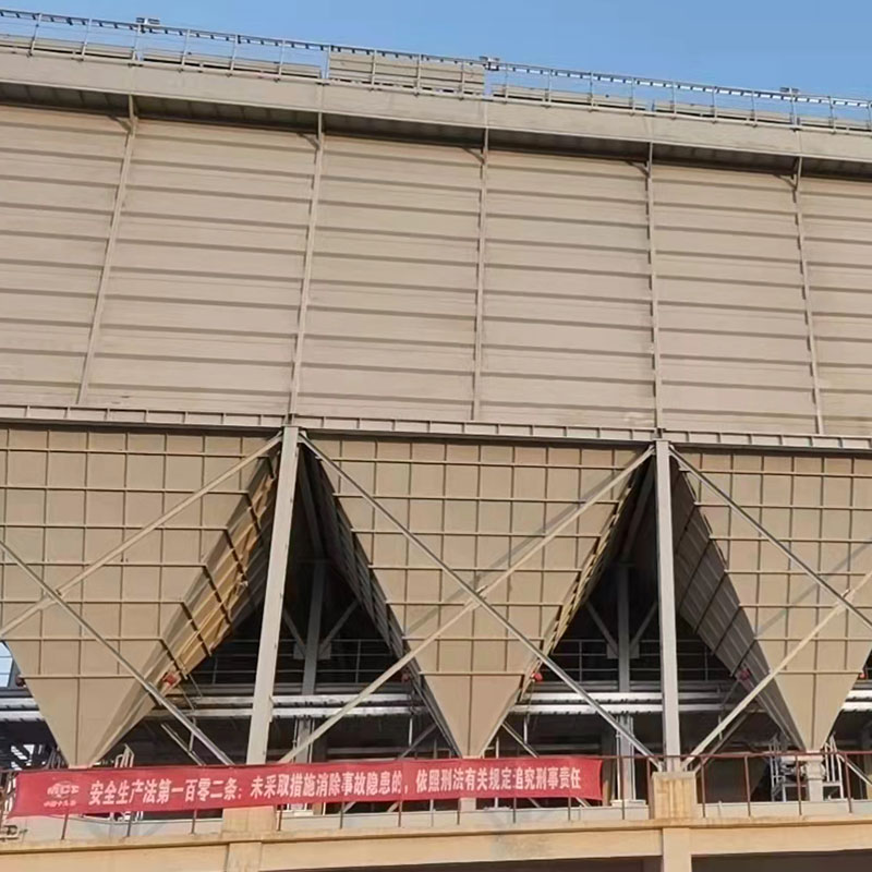 Low-Pressure Pulse Jet Bag Dust Collector for Fine Dust ControlThis baghouse uses pulse-jet cleaning for dry, non-hygroscopic dust, achieving emissions below 8 mg/Nm³. It suits various industries but not high-moisture or sticky dust.View Product →
Capture velocity is not a universal number. It ranges from 0.5 m/s for light fumes to 2.5 m/s for heavy abrasive dust, and the diagram must show the chosen value for each hood.
The diagram should show both volume in cubic meters per hour and velocity in meters per second for every branch. Velocity is what keeps the dust moving through the ductwork.
Volume and velocity are linked by the cross-sectional area. A 150 mm duct at 20 m/s transports about 1,270 cubic meters per hour. The same duct at 15 m/s transports roughly 950 cubic meters per hour. The diagram must show this calculation for each branch.
The most expensive mistakes are drawn before construction starts. Reviewing a diagram against the list below catches almost every field failure I have seen.
Branch airflow values missing
Long horizontal duct runs without inspection doors
Flexible connectors placed on the fan inlet instead of the outlet
Compressed air supply pressure below 0.5 MPa for pulse-jet cleaning
Hoods positioned too far from the emission point
No slope on horizontal runs carrying heavy abrasive dust
Each error has a clear field symptom: missing airflow values make it impossible to balance the system; long horizontal runs without access doors create hidden plugging; flexible connectors on the suction side collapse under negative pressure; low compressed air pressure leaves bags un-cleaned; a hood too far from the source wastes energy.
A simple check of the pressure drop across the filter unit can save weeks of troubleshooting. Plan for a cleaning cycle start at 1,500 Pa and a manual inspection above 2,000 Pa.
Start with a scaled floor plan and work from each hood back to the unit. For steelmaking furnaces, the hood geometry is the critical first element, and an electric furnace fully enclosed hood captures fumes at the source while reducing the total airflow requirement.
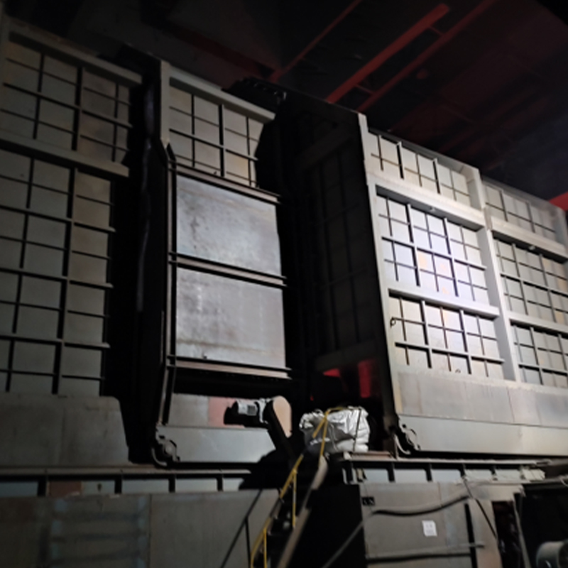 Electric Furnace Fully Enclosed Hood for Fume CaptureA fully enclosed hood that captures over 95% of fumes from electric furnaces, reduces noise by 20-25 dB, and features temperature monitoring and explosion relief.View Product →
List every capture point and measure the actual process dimensions. Include elevation differences because vertical risers change the pressure balance.
Calculate the required airflow for each hood based on capture velocity and hood opening area.
Choose a standard duct diameter to keep velocity within the conveying range.
Compute branch and main duct pressure losses, including elbows and flex hoses.
Select the fan and motor based on system resistance plus a 10 to 15 percent margin for dust cake buildup.
Mark slope of 1 percent or more for horizontal runs and place inspection doors every 3 to 4 meters.
In field measurements, the total system pressure drop is the fan static pressure when the fan runs at design speed with no leaks. A diagram that does not let you calculate this value is incomplete.
Dust size and abrasiveness determine the filter media, duct velocity, and hood geometry, so the diagram cannot be designed without a dust sample.
Compact footprint, good for fine dry dust. Filtration velocity 0.8 to 1.2 m/min. Use the low-pressure pulse-jet filter cartridge dust collector when space is limited and dust is not abrasive.
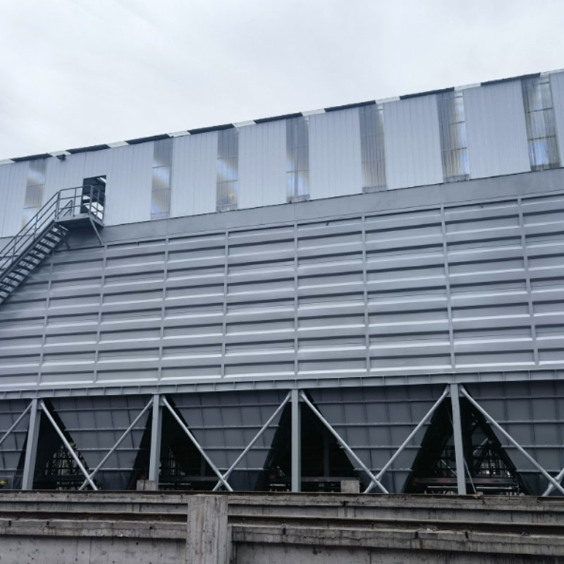 Low-Pressure Pulse Jet Filter Cartridge Dust CollectorCompact cartridge collector for fine dry dust, with lower filtration velocity and space-saving design. Suitable for non-hygroscopic dust at temperatures below 150°C.View Product →
Robust, suitable for abrasive and hot dust. Filtration velocity 1.0 to 2.5 m/min. The bag configuration allows long bags for a larger filter area in a narrower footprint.
For abrasive quartz dust, use a duct velocity above 20 m/s and a filter bag with a reinforced bottom. The diagram must also show a drop-out box or cyclone before the filter unit for heavy particles. For more details on how baghouse systems perform across industries, see our article on bag filter dust collectors as guardians of industrial purity.
The capture velocity at each hood. For dust with a particle size above 100 micrometers, a capture velocity between 1.5 and 2.5 m/s is typical.
Pulse-jet cleaning requires a minimum pressure, usually 0.5 to 0.6 MPa. If the drawing does not specify the air supply and header diameter, the filter bags will not clean properly.
Check for three values: branch airflow, main duct velocity, and fan static pressure. If any one is absent, the drawing cannot be used for commissioning.
Use a cartridge collector for fine, dry, non-abrasive dust with a filtration velocity of 0.8 to 1.2 m/min. Choose a baghouse for abrasive or hot dust.
Remember: a diagram is a decision tool, not a decoration. Use it to verify capture velocity, duct velocity, and fan static pressure before you sign off on the system.