English
 Français
 عربى
 简体中文


Dust Collection System Design: A Practical Engineering Guide for Industrial Plants
HOME / NEWS / Industry News / Dust Collection System Design: A Practical Engineering Guide for Industrial Plants
 By Admin
Content
A steel mill's pulse-jet baghouse held a steady 6 in. w.g. of differential pressure, but a visible dust plume still escaped from the transfer tower. The audit traced the fault to the hood: capture velocity at the transfer point measured 92 fpm against a 400 fpm design target. Branch dampers had been throttled to protect one overloaded hopper, and every hood on that trunk lost velocity. The pattern repeats across plants in every sector, and it starts upstream of the filter. It starts with dust collection system design.
An industrial dust collection system performs three sequential jobs: capture contaminated air at the source, convey it through ductwork at a velocity that prevents settling, and separate the particles in a collector before clean air is exhausted. The stages share one pressure budget and one fan curve, so designing them as independent components produces the classic failure mode: a collector that performs perfectly at the test bench but cannot protect anyone on the plant floor. The governing engineering reference is the ACGIH Industrial Ventilation manual, and its core message is that capture happens at the source, not at the filter.
Capture velocity is the first number to fix in any dust collection system design because it decides whether the dust ever enters the system at all. It is the minimum air speed at the point of dust generation required to overcome room air currents and process-induced draft and pull the contaminant into the hood.
The recommended value depends on how energetically the dust is released. A release into relatively calm air can be captured at 100 fpm; molten metal tapping, furnace charging, and high-speed grinding throw particles hard enough that 200 to 500 fpm is needed at the point of generation. The ACGIH Industrial Ventilation manual specifies these target values and warns that capture velocity must be measured at the source, not at the hood face.
| Emission source | Capture velocity (fpm) | Hood configuration |
| Blast furnace taphole | 200-500 | Side-draft hood or full enclosure |
| Electric furnace charging | 150-300 | Full canopy or enclosed hood |
| Converter front | 200-400 | Front capture hood |
| Belt conveyor transfer | 300-400 | Belt-enclosed hood |
| Grinding and polishing | 500-1,000 | Close-capture local exhaust |
Hood geometry is just as decisive. An enclosed or tightly shrouded hood, such as a belt-enclosed hood on a conveyor transfer, needs roughly one third of the exhaust volume of an open canopy for the same capture result. That factor repeats on every hood in the plant and multiplies directly into fan size, duct diameter, and annual energy consumption. For furnace operations, a converter front capture hood should be positioned so the furnace mouth sits inside the capture window before tapping begins.
In electric arc furnace shops, a fully enclosed furnace hood surrounds the vessel and catches the charging and melting fugitives that no canopy can control; the enclosure converts a violent release into a controlled draft that the rest of the system can handle.
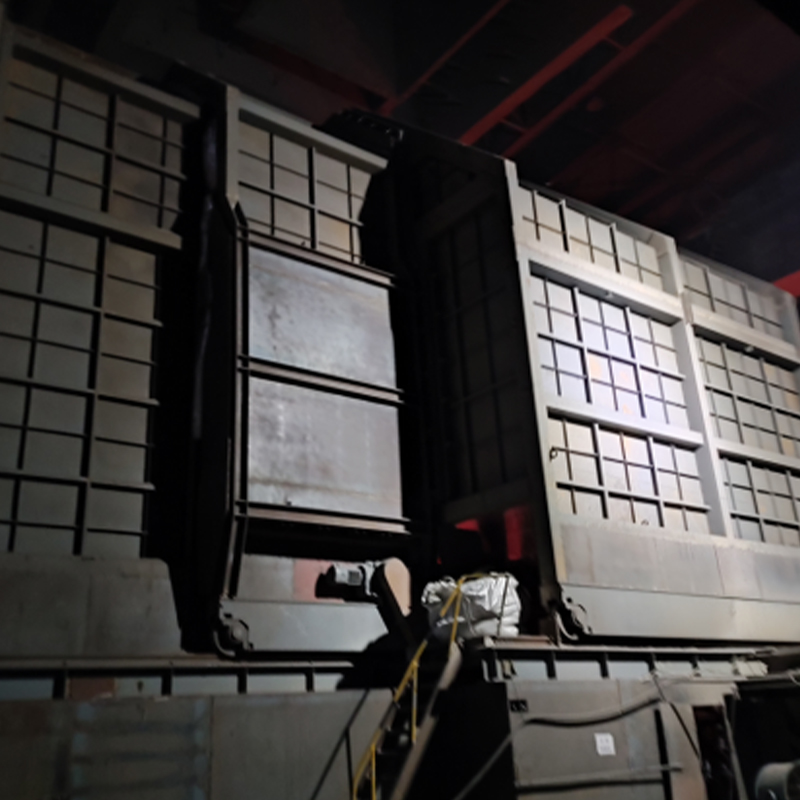 Fully Enclosed Electric Arc Furnace Capture HoodThis hood encloses the furnace operation area for full-process fume collection, achieving over 95% capture rate and reducing noise by around 25 decibels, making it essential for controlling fugitive emissions in steel shops.View Product →
Every branch duct must hold a minimum conveying velocity, typically 3,500 to 4,500 fpm for industrial dust, and the static pressure loss of every branch must be equalized so that no single hood short-circuits the system. Conveying velocity is the air speed inside the duct, and it has one purpose: keep the particles suspended until they reach the collector.
The ACGIH manual gives minimum conveying velocities by dust type. Fine wood sanding dust stays suspended at 3,500 fpm; cement and lime dust need about 4,000 fpm; metal grinding fines and plastic buffing fibre require 4,500 fpm. Sizing a mixed system to a single average velocity will silt the duct on the denser dust or waste static pressure on the lighter one.
Minimum duct conveying velocities recommended for common industrial dusts, based on the ACGIH Industrial Ventilation manual.
The most common design error in a multi-hood network is laying out the ductwork symmetrically and letting the system sort itself out. It cannot. The branch closest to the fan has the shortest run and the least resistance, so it draws more than its designed share of air while distant branches lose velocity and begin to silt. The correct practice is to size each run so that the static pressure losses of all branches are equal at design flow, then install balancing dampers and verify every hood with an anemometer.
The duct design sequence that prevents this failure is short and repeatable:
Map every emission point and assign a capture flow to each hood.
Route mains and branches with 45-degree entry angles and long-radius elbows.
Calculate the pressure loss of every run and equalize the branch sizes.
Select the main trunk diameter above the settling threshold for the dust mix.
Add test ports and clean-out doors to every section, and document a target velocity for each hood.
If space constraints force rectangular ductwork instead of round, add a velocity margin of 15 to 20 percent above the round-duct recommendation.
Best hydraulic efficiency, lowest pressure loss, and self-cleaning at design velocity. The default choice for conveying dust.
Compact in tight spaces but creates corner eddies where dust settles; use it only with a conveying velocity margin of 15 to 20 percent.
The collector is selected on dust characteristics: particle size, temperature, moisture, abrasiveness, and combustibility, not on air volume alone. A baghouse, a cartridge dust collector, an electrostatic precipitator, and a wet scrubber each serve a different combination of conditions, and a mismatch surfaces quickly as blinding, corrosion, bag wear, or emission exceedances.
For dry, hot, abrasive, high-volume dust, such as the dust generated in steelmaking, sintering, cement kilns, and foundries, a pulse-jet baghouse is the workhorse. Its fabric filter operates continuously at gas temperatures up to 260 C with the correct media and returns well over 99 percent of collected PM to the process. It is also designed to clean itself: a pulse-jet baghouse typically runs at 4 to 6 in. w.g. of differential pressure, and a steady climb above that range means bag cleaning is failing long before the bags wear out.
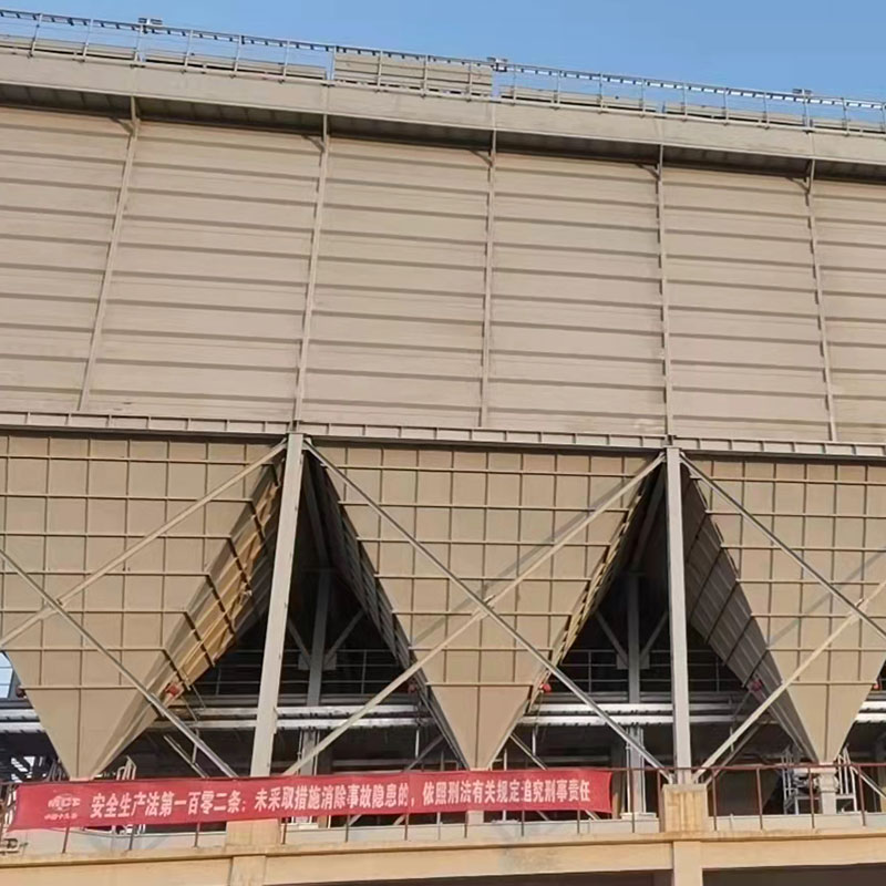 Low-Pressure Pulse Jet Baghouse Dust CollectorA pulse-jet baghouse suited for dry, hot, abrasive, high-volume dust like steelmaking, with continuous operation up to 260°C, self-cleaning bags, and outlet emissions below 8 mg/Nm³, ideal for demanding industrial processes.View Product →
Where the dust is fine, dry, and lower in volume, such as metal powders, pharmaceutical granulates, and reclaimed sand, a cartridge collector packs more filtration area into a smaller footprint with pleated media. Cartridges exceed 99.9 percent efficiency on fine particles but operate at 80 to 120 C, so a hot process needs a cooler or dilution leg upstream.
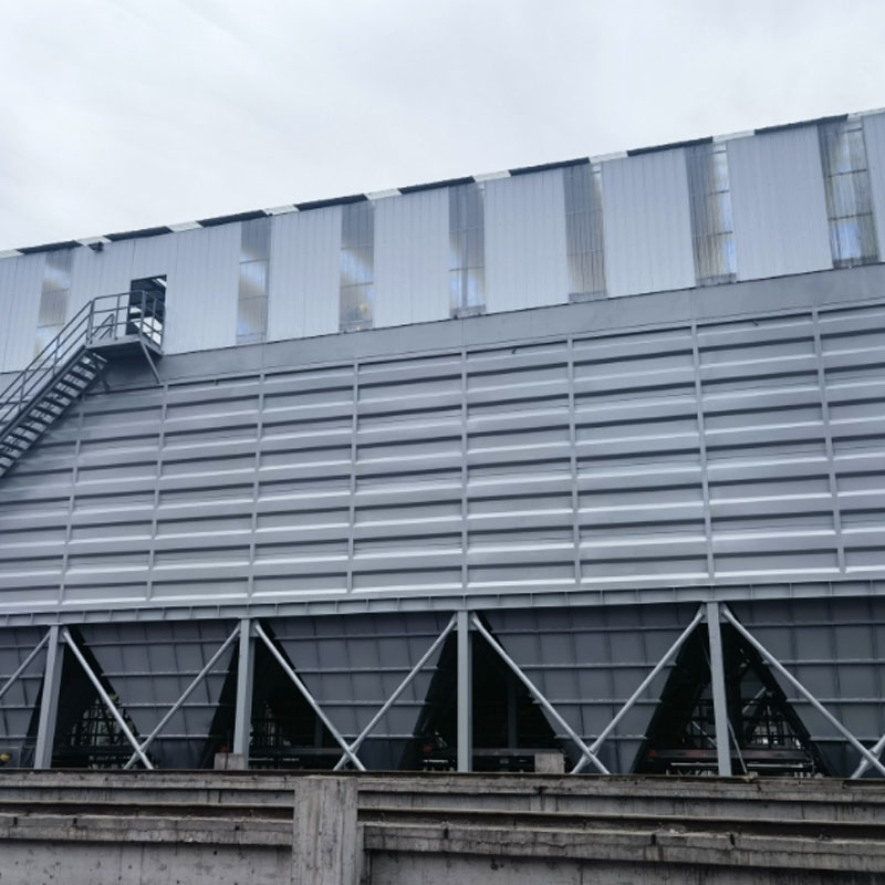 Low-Pressure Pulse Jet Cartridge Dust CollectorThis cartridge collector packs more filtration area into a smaller footprint for fine, dry dust, requiring lower wind speeds and offering cost savings on space, but limited to under 150°C operation—check hot-process compatibility.View Product →
At the opposite end of the scale, an electrostatic precipitator handles very large gas volumes with fine particulate at temperatures that would destroy fabric filters, which is why sinter strands and power boilers use them. Wet scrubbers take over where dust is sticky, hygroscopic, or potentially explosive, because the water phase removes the ignition risk and the wet discharge avoids re-entrainment.
| Technology | Typical efficiency | Continuous temp. limit | Best service conditions |
| Pulse-jet baghouse | 99-99.9% on PM | Up to 260 C with suitable media | High-volume dry dust; steel, cement, foundries |
| Cartridge collector | 99.9%+ on fine dust | Up to 120 C | Fine powders, low to medium volume, high air quality demands |
| Electrostatic precipitator | 97-99.5% | Up to 400 C | Very large gas volumes; sinter strand, power boiler |
| Wet scrubber | 95-99% | No practical limit; cools gas | Moist, sticky, or combustible dust; acid and odour duty |
Turnkey suppliers such as Anhui Tiankang Environmental Technology Co., Ltd. deliver the capture hoods, ductwork, and collector as one engineered package, which is the practical way to enforce the system-level thinking this design sequence requires.
A dust collection system that is balanced runs at a stable, predictable pressure drop; an unbalanced one burns extra energy and converts maintenance hours into lost production. The fan curve makes the consequence concrete: at constant fan speed, a 10 percent rise in system resistance cuts total airflow by roughly 8 to 10 percent, dropping the ducts below conveying velocity and guaranteeing silting.
Monitoring turns these numbers into a maintenance program. A differential pressure logger on the collector, a fixed anemometer at one reference point per trunk, and a quarterly velocity traverse of each hood will find the failure before a regulator does. A hood that has lost 30 percent of its velocity is nearly always a balancing problem or a closed damper, not a filter problem. The baghouse is reporting upstream conditions, not its own health.
These are the questions plant engineers ask most often once the basics of capture velocity, conveying velocity, and filter selection are clear.
Capture velocity is the air speed at the dust release point that pulls contaminants into the hood, typically 100 to 500 fpm depending on the process. Duct conveying velocity is the air speed inside the ductwork that keeps dust suspended, normally 3,500 to 4,500 fpm. Both must be set explicitly in the design; neither can be left to chance.
Because the nearest branch has the shortest duct run and the least resistance, so it takes a disproportionate share of the total flow. The fix is to size each branch so the static pressure losses of all runs are equal at design flow, add balancing dampers, and verify each hood with a velocity measurement.
Size the collector and the fan for at least the five-year production plan, and lay out the duct mains with capped tee connections so later branches can be added without rebalancing the entire network. A 10 to 15 percent margin on filter area also lengthens bag and cartridge service life.
If the dust is combustible, such as metal fines, coal, sugar, wood, or many plastics, NFPA 652 requires a Dust Hazard Analysis and protections that can include venting, suppression, and isolation. Testing a representative dust sample for explosibility is the first step of that analysis.